In this article, we will study the Definition, Types, Working Principles, Advantages, Disadvantages, and Applications of a Cam and Follower in detail.
Note: You can download PDF of this article at the end.
Let’s start with the definition of Cam,
When the two links are connected either along a line or at a point, it is called a higher pair. Two such higher pair mechanisms will be included in a cam-follower system. A higher pair mechanism is known as cam and follower.
For the smooth functioning of a cam-follower mechanism, it is imperative that the follower should move smoothly without requiring too much input power, which means the follower should not jam, during its movement.
In an IC engine the valves have to be kept open; first, then close it and keep it closed, all these timing operations can be easily set by having cam-follower mechanisms.
In the case of linkages, we study planar linkages or two- dimensional linkages, and more.
Now moving to different types of Cam,
The following five types of CAM:
A disc or plate cam is a type of cam in which the follower moves radially from the center of rotation of the cam. These cams are very popular due to their simple design and compactness that can be fitted into remote places. The application of Disc or Plate Cam is in I.C engines and machine tools.
A Cylindrical cam is the cam in which the cylinder rotates about its axis has a circumferential contour cut on the cylinder surface. They are also of two types in the first type a groove is cut on the surface of the cam and the roller and has a positive oscillating motion.
Another one is having a cylinder as the working surface. In this type of cam spring-loaded follower translates along the parallel axis to the rotating cylinder.
Translating cam is the type of cam in which cam can move in a horizontal plane. The follower attached too has the motion constrained with the help of the spring. Sometimes groove cams are used in which the follower motion is achieved without the use of the spring.
If the input link also called cam rotates as angular motion, then the cam has rotational or angular motion and then we call it a radial cam.
This profiled body is called the cam. This has a revolute pair with the fixed link that is the foundation or fixed link. Cam is the revoluting link. There is a revolute pair between the fixed link and the cam and the output link is the follower.
If this cam rotates depending on the profile or shape of the cam, the follower will have translatory motion along with this prismatic pair between the fixed link and the follower.
So uniform rotary motion of this cam will have oscillation of the follower along with the guide.
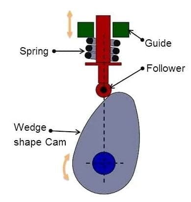
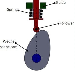
If the cam has a linear motion, then we call it a wedge cam. Wedge cam has a four-link mechanism, first is the fixed link, the cam which looks like a wedge is the other link.
It depends on the profile of this wedge, as this cam oscillates in the horizontal direction, the follower will oscillate along the vertical direction along with this prismatic pair or this guide.
Now we are moving to follower,
A follower is a translating or oscillating mechanical member that follows the motion of the cam. It can touch the surface profile of the cam or can be spring-loaded. It can have a uniform velocity or can have uniform acceleration motion. Complicated output motion can be achieved with the help of the follower motion.
The six different types of followers are:
If the follower has linear motion, then we call it a translating follower. Now for the translating follower, that is the axis of that prismatic pair passes through the cam center, then we call it radially translating.
We call it a radial translating follower when the follower axis passes through the center of the camshaft. If it has a little offset, that means the axis of the translation of the follower does not pass through the cam center, then we call it an offset translating follower.
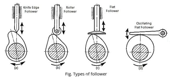
The cam rotates as before but this is the follower due to the shape of the cam, the follower undergoes an oscillatory motion and the follower is hinged at this point. So, this is called an oscillating follower.
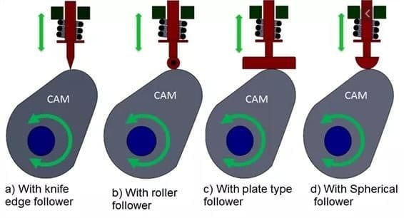
If the follower has just a knife-edge with the cam then we call it a knife-edge follower. the knife-edge is only theoretical because knife-edge follower is never used because of the very high wear rate. Contact stress will be extremely high.
The follower is hinged to a roller and this roller is in contact with the cam, this is called roller follower. This is the cam that rotates and the follower which is hinged here oscillates. it is used when a large force has to be transmitted like in stationary IC engines.
If there is not enough space to use a large roller because this pin has to be sufficiently big to transmit the force between the cam and the follower and the roller has to be bigger than the pin at least twice as big as the pin, then the roller needs a lot of space.
The follower surface which is in contact with the cam is in the form of a flat surface is called a flat face follower. The follower surface, instead of flat, can be also a curved surface.
This is the cam that rotates and the follower which is hinged here oscillates, so this is called curved-face. If space is restricted then we can use a flat face follower, if the force involved is not too large as we used in the case of automobiles.
The following terminology of Cam and Follower is:
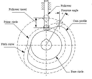
Tracepoint is a point on the follower, which describes the follower movement. For roller follower, it is the center of the roller. So the tracepoint is the roller center, which means the movement of the follower will be described in terms of the motion of this roller center.
If it is a flat face follower, then the tracepoint we use is the point on the follower’s face that is in contact with the cam surface when the follower is at one of the extreme positions, we normally use that extreme position when the follower is closest to the cam center.
The base circle is the smallest circle that can be drawn with the cam center as the center and touching the cam profile, this circle we call a base circle. So the radius of the base circle we call, Rb, is called the base circle radius.
To define the pitch curve, think of kinematic inversion. In the kinematic inversion, this is a four-link mechanism, fixed link, cam, roller, and follower.
In this four-link mechanism, this link is fixed, but in the kinematic chain, if we make a kinematic inversion holding cam fixed. the locus of the center of the roller will generate a curve that is parallel to the cam profile.
This is the locus of the tracepoint or roller center, after kinematic inversion with cam fixed.
The smallest circle can be drawn with the cam center as the center and tangential to the pitch curve. This circle has a center at the cam-shaft axis and is tangential to the pitch curve. This circle is called the prime circle. If the base circle radius is Rb and Rr is the roller radius, then the prime circle radius is Rp = Rb + Rr.
The common normal between the roller and the cam is passing through the roller center and normal to the cam profile.
A normal force acts in the X direction and a normal force acts in the Y direction and these two normal forces balance the cocking moment, the moment due to this force Fn.
The friction force which will try to oppose this vertical motion will be μ times the normal force. The normal force is N, then this will be μN. During upward motion, the follower has to overcome not only these two friction forces but also has to overcome the spring force.
Large Fn is necessary to overcome the friction force and the vertical component of the Fn will overcome these two friction forces and the spring force, whereas during the downward movement the spring force is helping the follower to come down, so the contact force will be less.
The vertical component will be Fn cos φ, if the φ is very large then this vertical component will be reduced. As a result, during the upward movement, the pressure angle should be low and during the return movement, φ can be large, so φmax is more critical during the upward movement.
While designing a cam-follower system, translating follower does not jam in its prismatic guide. The chances of the restriction to the movement of the oscillating follower are much less.
The following advantages of Cam and Follower are:
The following disadvantages of Cam and Follower are:
Uses or Application of CAM and FOLLOWER is: